
Garage Door Opener Wiring Explained Safely
Garage Door Opener Wiring Explained Safely
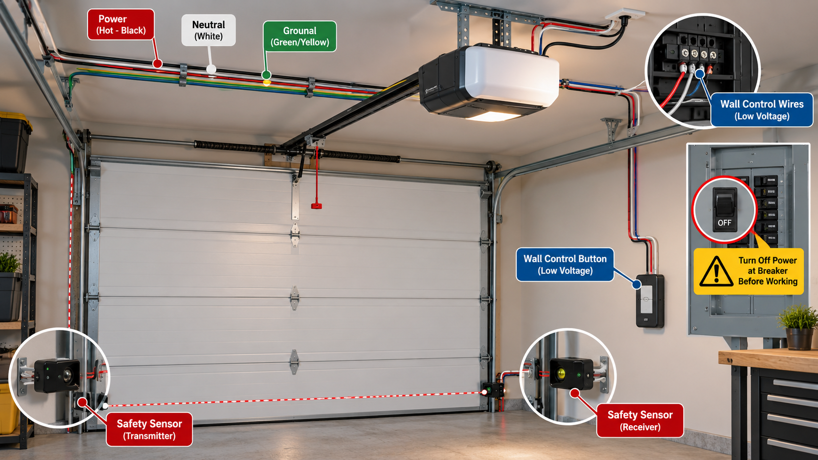
Garage door opener wiring is easier to understand when you separate it into distinct systems. The ceiling unit receives household power, while small low-voltage wires usually connect the wall control and photo-eye safety sensors. Some models also include a battery, camera, network module, lock, or accessory terminals. These circuits do different jobs and must not be treated as interchangeable.
There is no universal terminal layout or wire-color diagram for every opener. Use the model number to find the manufacturer’s manual before moving any wire. This guide helps identify the circuits, diagnose symptoms, and recognize work for a professional.
Understand the three main wiring paths
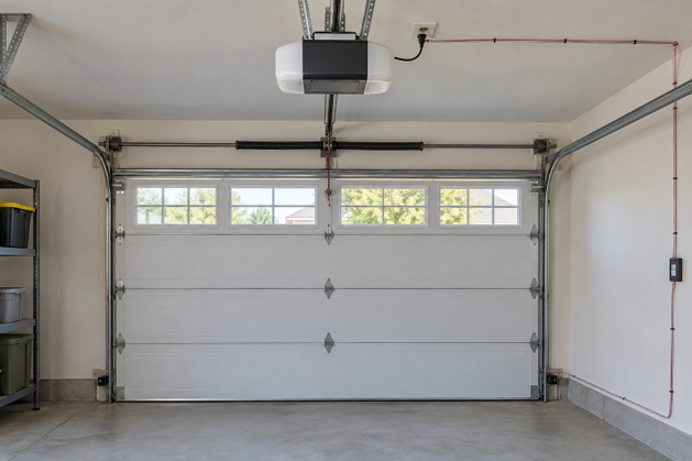
Household power to the opener
Most residential ceiling-mounted openers connect to a grounded receptacle near the motor unit. This is line-voltage power, not the same as the small wires on the accessory terminal strip. If a receptacle must be installed, moved, grounded, or repaired, use a qualified electrician and follow local electrical requirements. Do not splice a power cord into sensor wire or hardwire an opener unless the manufacturer’s instructions and local rules specifically allow it.
Before inspecting low-voltage terminals, unplug the opener and disconnect its backup battery if the manual requires it. A wall button that is dark and sensors with no indicator lights can point to lost power, but first test the outlet with an appropriate known-good device only if you can do so safely. Check a tripped breaker or GFCI device without opening electrical boxes. If power repeatedly trips, stop and have the branch circuit and opener inspected.
Low-voltage wall-control wiring
The wall control sends commands to the opener through one or more small conductors. Older push buttons may operate as a simple dry contact, while newer smart panels can exchange data and require a specific compatible control. A generic doorbell button or a wire pair copied from another brand may not work and could damage electronics.
Many terminals are identified by a symbol, number, or label rather than by color alone. Wire insulation colors can change during repairs, and installers sometimes reuse existing cable. Record the terminal positions before disconnecting anything. The Chamberlain D2101 support page, for example, links the exact installation manuals and lists the wall control, sensor kit, bell wire, terminal block, and other model-specific parts.
Low-voltage safety-sensor wiring
Photo-eye sensors form an invisible beam across the door opening. When an object interrupts that beam while the door is closing, the opener should reverse according to its design. The two sensors need correct mounting, alignment, compatible wiring, and secure terminal connections. Never bypass or permanently defeat this safety system.
The Genie Safe-T-Beam documentation explains that its paired sensors detect an obstruction and reverse the closing door, while its diagnostic lights report installation or operating faults. Chamberlain likewise provides dedicated safety-sensor replacement instructions for compatible models. These sources illustrate why the correct manual matters: terminals, polarity rules, indicator behavior, and compatible parts vary.
Five connection groups you may see
- Power input: a factory cord and grounded outlet, or a manufacturer-approved hardwired arrangement. This side contains hazardous voltage and is outside the scope of casual terminal troubleshooting.
- Wall control: a low-voltage pair or proprietary data connection running from the opener to the push button or smart console. A lock or vacation mode on the control can disable radio remotes without indicating a wiring failure.
- Safety sensors: one cable from each photo eye, sometimes joined before reaching the opener and sometimes landed separately. Maintain the wire pairing and polarity shown in the manual.
- Backup battery: an internal or enclosed connection on supported models. Disconnect it only as directed because the opener may remain energized after the power cord is unplugged.
- Optional accessories: locks, lights, cameras, keypads, or network modules that require the exact compatible port or wireless protocol.
How to read the model-specific diagram
Start with the opener’s model number, not the name printed on a remote. Search the manufacturer’s support site for the installation manual that matches that number and revision. Verify the cover image, production range, or logic-board designation if the manufacturer separates multiple versions under one product family.
On the diagram, trace one circuit at a time. Find the wall-control terminals and follow their conductors to the console. Then find the sensor terminals and follow each pair to the bottom of the tracks. Identify any shared common terminal, polarity mark, stripe, or push-in connector exactly as shown. Do not assume that a red wire must land on a red terminal after a previous splice.
Take a clear photo before removing a conductor and label the cable by destination, not only by color. If the old installation differs from the manual, pause; a mismatched board or older safety system may require a compatibility check.
Safe low-voltage inspection steps
With the door closed, unplug the opener and follow the manual’s battery-disconnection procedure. Keep the rail, trolley, chain or belt, door arm, springs, and cables untouched. Inspect the visible low-voltage cable for crushed insulation, corrosion, loose splices, and staples driven through the jacket. Replace unsafe fastening methods with approved loose clips only when the cable type and route are confirmed.
At a spring terminal, use the release as the manual directs and insert the specified stripped length without exposed copper. Do not combine extra conductors unless the diagram permits it. Confirm retention, then restore power and run the prescribed tests.
If you are replacing the complete unit, check whether existing control and sensor cable is compatible, undamaged, and correctly routed. The guide on replacing a garage door opener covers the broader decision, while the article on opener installation time explains why wiring, mounting, and testing can extend the job.
Diagnose symptoms without jumping terminals
Nothing on the opener works
Confirm power at the receptacle, the breaker, any GFCI protection, and the opener’s cord connection. A power outage may also leave the trolley disconnected or settings in an unexpected state; use the power-outage troubleshooting guide for that sequence. If the outlet is dead or damaged, call an electrician. If the outlet is good but the opener remains dark, internal service may be required.
The remote works but the wall control does not
This pattern points toward the wall console, its cable, or its assigned terminals rather than the motor’s main power. Check for a loose conductor or damaged cable only after de-energizing the unit. Verify that the replacement control is compatible; modern multifunction panels may not behave like a simple push button.
The wall control works but remotes do not
Wall-control wiring is probably carrying commands. Check the control’s lock mode, remote battery, programming, and radio interference before changing wires. The site’s guide to a remote garage door opener not working separates radio problems from wired-control faults. For a Craftsman unit, use the model-aware steps in the Craftsman remote programming guide.
The door opens but will not close
Look for an obstruction, dirty lens, misaligned sensor, loose sensor wire, or damaged cable. Indicator lights and opener flash codes are model-specific, so read the diagnostic table before interpreting them. Do not move the sensors above the manufacturer’s permitted height or hold a wall button as a permanent workaround.
The opener beeps or behaves intermittently
Beeps can indicate a battery, close warning, setup state, or fault. Check the garage door opener beeping guide, then confirm the meaning in the manufacturer’s manual. Intermittent operation can come from staple damage, a loose splice, moisture, or an aging board.
When to stop and call a professional
Stop if the problem involves a damaged outlet, repeated breaker trips, overheated insulation, arcing, an internal power-supply board, or uncertain line-voltage wiring. Use an electrician for the household circuit and a trained opener technician for model-specific internal repair. Also stop if troubleshooting would require moving springs, cables, bottom brackets, or the door while it is not safely balanced.
A professional should also handle undocumented modifications, incompatible controls, corroded terminals, multiple mystery splices, or a safety system that cannot pass the manufacturer’s reversal test. Replacing a wire is not a complete repair unless the door closes, reverses, and responds to every control exactly as the manual specifies.
Frequently asked questions
Are garage door opener sensor wires low voltage?
They are normally part of a low-voltage control circuit, but the exact voltage and connection method depend on the opener. Keep them separate from household power and follow the model manual.
Can I reuse the old wall-control and sensor wires?
Only if the new opener permits it and the cable is compatible, continuous, undamaged, and routed safely. Replace cable with crushed insulation, hidden corrosion, unsafe splices, or staple damage.
Do wire colors match across opener brands?
No. Colors are useful identifiers only after you trace the cable and confirm the terminal diagram. Never transfer a color pattern from a different model.
Can I bypass the safety sensors to test the door?
Do not permanently bypass or defeat them. Use the manufacturer’s diagnostic procedure and repair the sensor, alignment, connection, or cable fault before normal operation.
Use the manual as the final wiring authority
Garage door opener wiring becomes manageable when you distinguish household power, wall-control conductors, sensor conductors, battery connections, and accessories. Photograph the original terminal layout, identify cables by destination, and follow the exact manual instead of a generic color chart.
Limit homeowner work to safe, de-energized, model-approved low-voltage checks. If the fault reaches mains power, internal electronics, safety-system bypasses, or moving door hardware, stop and call the appropriate professional. Correct wiring is proven by a complete functional and safety test, not simply by a motor that runs.